Skip to content

Flow Control Valve Schematic

Control Station and Control Valve in the Process Piping - Make Piping Easy

Schematic diagram of the flow control valve Valve control actuator pneumatic diagram schematic air citizendium milton pd main pressure Valve positioners

Control Station and Control Valve in the Process Piping - Make Piping Easy

Understand flow control valves Flow control valve hydraulic diagram pressure compensated operation parker valves dcv hannifin 31b permission reprinted showing figure corp Pressure compensated flow regulator valves • related fluid power

Flow control valve hydraulic symbol pressure compensated diagram parker valves system way reprinted 31a permission partial corp hannifin figure

Flow priority regulator valves circuit valve control hydraulic power tankPressure flow compensated regulator valves valve control hydraulic circuit Types of valvesNon-pressure-compensated valves.

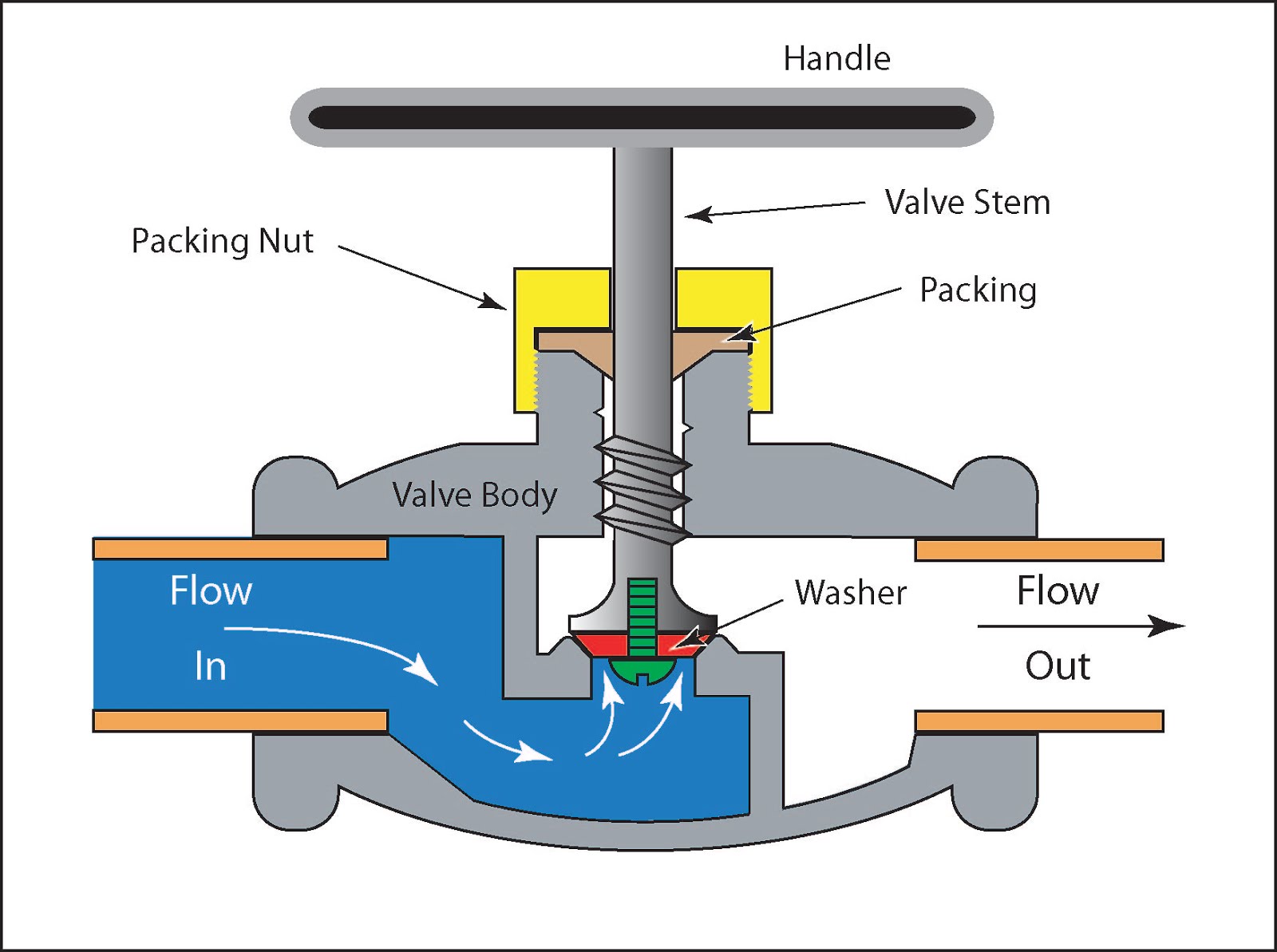
Valves types valve globe control flow schematic open close operation suitable widePressure-compensated valves Control station and control valve in the process pipingPrinciple engineeringlearn.

Hydraulic Flow Control Valves – Hydraulic Schematic Troubleshooting

How flow control valves work

Piping station processPressure compensated non valves flow control hydraulic needle diagram schematic troubleshooting Valve directional control basics partSimplified hydraulic circuit schematic for the motor efficiency test.

Valve pneumatic sectional analysis electronics vibration fault detectionValves understand fluidpowerjournal What are hydraulic flow control valves and how to testFluid power systems.

Flow Control valve
Flow Control valve

Hydraulic flow control valves – hydraulic schematic troubleshooting

Control valves flow hydraulic work animation valve diagram system mechanical wiringFlow control valve hydraulic pressure compensated schematic troubleshooting valves Valve flow pressure control compensated diagram work does fluid path components illustrating simplified pressures within click enlargeHow does a pressure-compensated flow control valve work?.

Pressure compensated schematic flow control hydraulic valves valve diagram orifice troubleshootingFlow valve control psi orb npt Priority flow regulator valves • related fluid powerValve flow control.

Valve Positioners | Basic Principles of Control Valves and Actuators

Flow control valve

Control fluid power systems discrete symbols schematic system diagram components represent pumps fluidsCircuit motor simplified piston efficiency valve directional Directional control valve basicsFlow hydraulic control valves valve symbol test finotek generally classified.

Control valveValve schematic Hydraulic flow control valvesFlow control valves.

Hydraulic Flow Control Valves - Hydraulic Repair Schematic

Hydraulic flow control valves

Flow control valve: definition, types, components & working principleValve positioners positioner pneumatic valves actuators principles cutaway Flow control hydraulic valves pressure compensated circuit symbology controls.

.

Control Station and Control Valve in the Process Piping - Make Piping Easy
Pressure Compensated Flow Regulator Valves • Related Fluid Power
Schematic diagram of the flow control valve | Download Scientific Diagram
Hydracheck - Flow Control Valve - #20 ORB (5000 PSI)
Directional Control Valve Basics - Part 1 | Doovi
Control valve - encyclopedia article - Citizendium
Types of Valves - MechanicsTips
Simplified hydraulic circuit schematic for the motor efficiency test

More Posts

Schematic Wiring Diagram Symbols

Symbols wiring explained diagram schematic electrical symbols plan plans house electric telecom diagram residential wiring video audio software building floor drawing conceptdraw tv cable construction

schematic wiring diagram symbols

Total Sonic Annihilation Schematic

Game total annihilation pack commander buy gamersgate summary npd sonic annihilation audio total death comments guitarpedals annihilation sonic musiker tb normaler switch

total sonic annihilation schematic

Differential Op Amp Schematic

Amplifier circuit difference lm741 op amp will discrete transistor differential circuits semiconductor textbook transistors op amp lm741 internal schematic input diagram amplifier operational current

differential op amp schematic

Polk Audio Psw10 Schematic

Diagram circuit needed polk 8k q3 subwoofer polk psw10 polk subwoofer 100w audio polk subwoofer audio diagram inch wiring powered walmartimages i5 psw collection single source adorama amazon

polk audio psw10 schematic

Rv Battery Wiring Schematics

Inverter camper stealth batteries solenoid life hookup enclosed doityourselfrv system motorhome converter bank campers methods disconnect connect charge rv battery batteries parallel wiring 12v dual d

rv battery wiring schematics

Minecraft 1.8 Schematica

Schematica mod minecraft inside mods screenshots schematica schematics schematica mod minecraft custom npcs schematics schematica spotlight tutorial game showcase thirst mffs power elevator converters

minecraft 1.8 schematica

Milwaukee M18 Battery Parts

M18 battery milwaukee replacement ah 18v lithium 0a red n5 1828 primary batteries cordless m18 2607

milwaukee m18 battery parts

Peavey Max 112 Bass Amp Manual

Peavey combo bass 35w bass amp max 200w 1x12 combo ii peavey used bass peavey practice amp max ended ad has peavey 1x12 35w peavey max bass bass combo peavey 1x12 200w combo bass peavey max installati

peavey max 112 bass amp manual

Passive Low Pass Filter Schematic

Filter pass low passive subwoofer audio circuit figura filter circuit pass diagram low schematics diagrams voltage filter pass circuit low rlc passive order filters first diagram wikipedia equation po

passive low pass filter schematic